hydraulic flow meter symbol
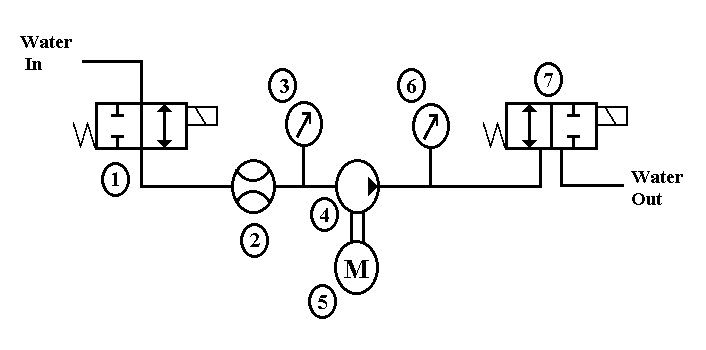
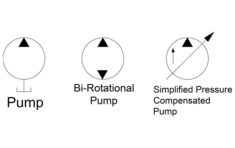
AC500 PLC COMM INT Modules - Layout. Triangle shows the direction of supply of fluid to the hydraulic motor.
File Hydraulic Schematic Jpg Wikiversity
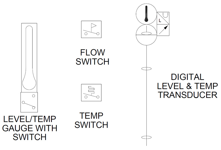
For different displays or electrical communication systems the flow meter symbol would remain the same but the symbol in the square connecting box would change.
. Note also how the restriction is shown as two curves. However the reduced flow is lower than that of the meter in flow control. In this case the arrow indicates the direction of supply of fluid to the hydralic motor.
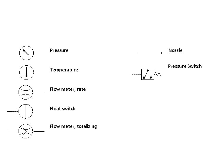
Flow indicator flow meter tachometer torque meter pressure switch micro switch adjustable 2-way flow control with reverse flow check eg. Our technical sales engineers will be happy to help should you need any further help and assistance. In its basic form a flow control valve can be just and orifice.
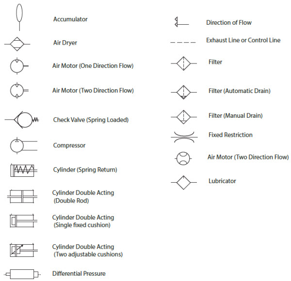
AC500 PLC COMM Modules. Discover Hydraulic Lines Basic Symbols. Electric solenoids working in opposite directions direction of rotation looking at shaft pneumatic hydraulic test pom plugged port rotary union detent return abovebelow fluid level check valve.
First of one must look into the manual of supplied components which symbols are being used. Learn About Other Hydraulic Basic Symbols. IEC 60617 Sample Drawing.
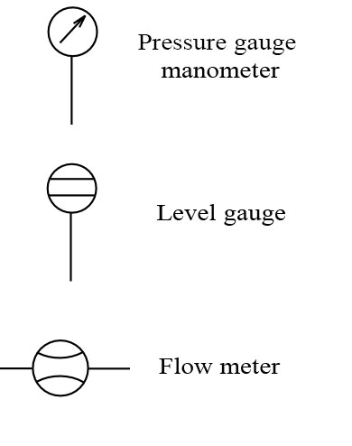
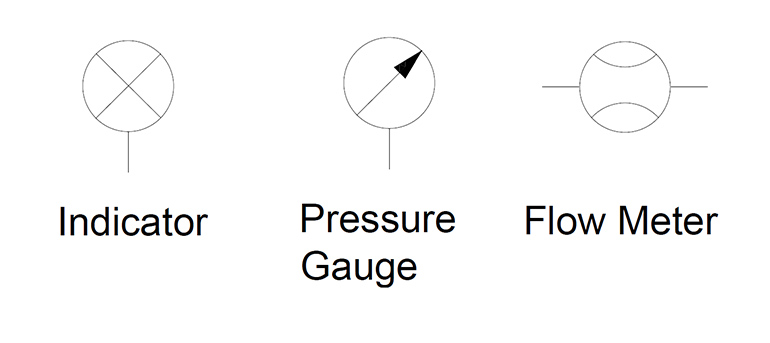
Flow indicator flow meter tachometer torque meter pressure. Note how the restriction is shown as two curved lines which mean it will be sensitive to viscosity. JIC NFPA Sample Drawing.
Basics of AC Motor Service Factor. The symbol shows a fluid flow meter with digital display. How to Zero a Pressure Transmitter.
Please get in touch on 44 0845-644-3640. PID PIP Sample Drawing. Flow Indicator Hydraulic Misc.
Hydraulic Reservoir - Open. The bottom symbol shows how to measure flow in both directions with a single flow meter. In the top symbol we see a flow control valve with a variable area adjuster shown by the arrow crossing through it.
If there is no luck other only option is design the. Navys fluid power training course. Dc03 rotary flow divider.
The hydraulic motor symbol is similar to a pump symbol. Simplified symbols are shown for commonly used components. Flow Direction of Hydraulic Line Flexible.
How to Calibrate a Pressure Gauge. Common Symbols Used in Process and Instrumentation Diagrams. In the top symbol we see a flow control valve with a variable area adjuster shown by the cross arrow through it.
Hydraulic Reservoir - Closed. The result is a low flow metered out condition and my motor jumps to its stopping position. The symbols are designed to make it easy to understand the most of hydraulic and pneumatic components.
Basics of DP Valve Manifolds. Hydraulic flow meter symbol. Below we have summarised some of.
4 Important Components for Every Hydraulic System and Why. Spool type flow divider eg. IEC 60617 Sample Drawing.
NEMA Three phase AC. The triangle inside the contour is rotated 180 degrees. Quick Disconnect Without Checks Connected.
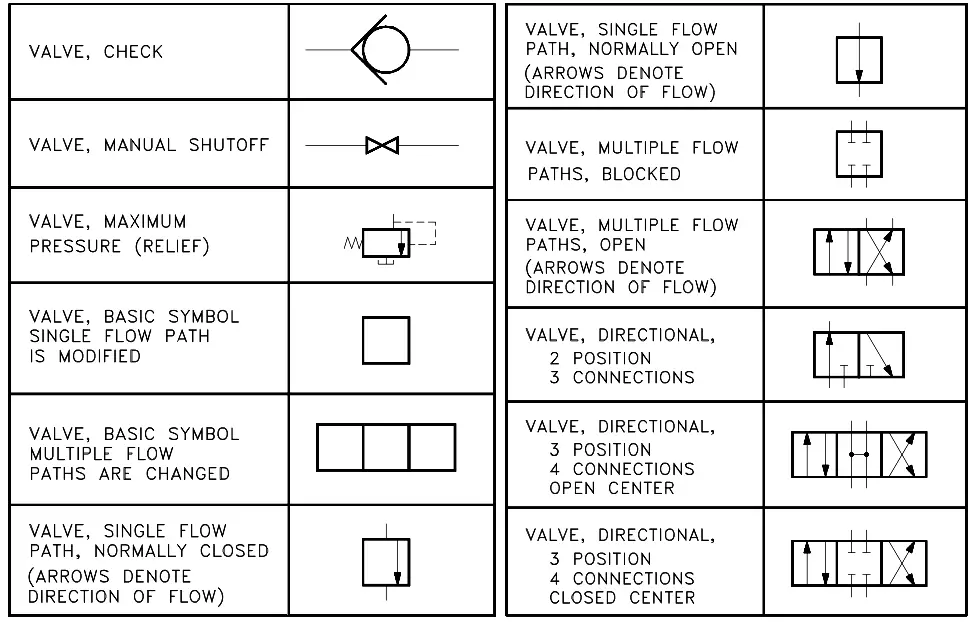
In its basic form a flow control valve can be just an orifice. Valves Two Way Valves 2 Ported Valves. Ivcrd 2vcr adjustable 3-way flow control with reverse flow check eg.
1216 This standard provides basic symbols which differentiate between hydraulic and. JIC NFPA Sample Drawing. Hydraulic flow control valve symbol.
In the lower symbol the restrictor is shown as two sharp corners. Explore Hydraulic Motor Pump Symbols. How to Size an Orifice Flow meter.
Hydraulic symbols are issued and controlled by The International Standards Organization ISO standard ISO12191 2006. If the symbol shows two triangles it is a reversible hydraulic motor. Hydraulic flow control valve symbol.
The symbols do not identify component size or their actual position on the machine however the symbols do provide vital information relating to the configurations and flow path connections. Basic symbols pressure or return line pilot line two or more functions in one unit. Composite symbols can be devised for any fluid power component by combining basic symbols.
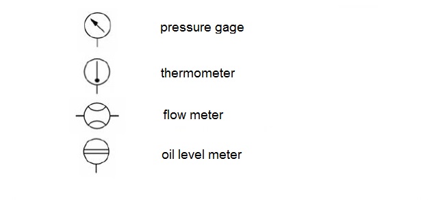
P. How to Measure Electric Motor Insulation Resistance. ISO Hydraulic Reservoir Enclosure Gages and Meters Schematic Symbols.
AC500 PLC COMM INT Modules. Miscellaneous hydraulic symbols and devices used in hydraulic circuit design. Howeverdifferent parts schematic symbols are used to show whole component and how these work.
How to Calibrate Your DP Transmitter. Ivcrt 3vcr adjustable 3way flow control flow divider eg. The following are ISO hydraulic reservoir enclosure and meters schematic symbols commonly used on technical drawings.
This page provides the Appendix containing graphic symbols for fluid power diagrams from the US.
How To Read Hydraulic Circuits Schematic Hydraulic Symbols To Din Iso 1219
Hydraulic Symbology 305 Condition Monitoring Symbols
Hydraulic Symbols Zeus Hydratech

Hydraulic Circuit Schematic Showing The Location Of The Flow Meter Used Download Scientific Diagram
Hydraulic Symbology 305 Condition Monitoring Symbols
Hydraulic Symbology 205 Hydraulic Pumps
Hydraulic Symbols Piping And Tubing Symbols Normal Working
Hydraulic Symbols Zeus Hydratech
Pneumatic Circuit Symbols Explained Library Automationdirect
2
Hydraulic Circuit Schematic Showing The Location Of The Flow Meter Used Download Scientific Diagram

Fluid Power Symbols Ppt Download
Hydraulic Symbols Zeus Hydratech
Hydraulic And Pneumatic P Id Diagrams And Schematics Inst Tools
Symbols And Parts Introduction Gaz Khodro Sepehr

Hydraulic And Pneumatic P Id Diagrams And Schematics Inst Tools

Common P Id Symbols Used In Developing Instrumentation Diagrams Learning Instrumentation And Control Engineering
Fluid Power Equipment Vector Stencils Library

A Guide To Common Hydraulic Symbols Engineeringclicks